Arduino 101
Last Updated 3 June 2024
The Hauptwerk projects pages describe the conversion of specific organ consoles, and the circuit diagrams and software code are in part
specific to the existing console hardware in each case, although the general principles should be useful in a wide range of scenarios.
The Ahlborn keyboards in Project 1 have the commonly used 8x8 diode switch matrix while the Makin keyboards in Project 2 have a more unusual serial shift
register scanning arrangement. Also the Ahlborn keyboards have a 74138 TTL three to eight way decoder chip on board, so it is only necessary to use three
digital outputs on the Arduino board to drive the matrix rows. These three outputs can be paralleled across two or more keyboards and the 74138 chip-enable
input driven from further digital outputs on the Arduino to determine which keyboard is actually scanned. In this way the eight output lines from the 8x8
switch matrices can be paralleled and the whole thing fits within the twenty I/O pins available on an Arduino (fourteen plus the six analogue lines that
can also function as digital I/O).
By wiring a 74138 into the pedalboard reed switch 4x8 matrix it would have been possible to interface both manuals and the pedals
using a single Arduino and still scan all 154 contacts fast enough to avoid any perceptible lag (latency), and I did try this just
to prove the point.
Hauptwerk Project 3 had keyboards incorporating diode matrix switching, but the pedalboard was challenging and needed hardware
adaption of the switch contacts and special software to achieve reliable operation. In addition the illuminated tab stops
required handling Hauptwerk output commands and a way to identify each Arduino board as reported by the Windows USB drivers.
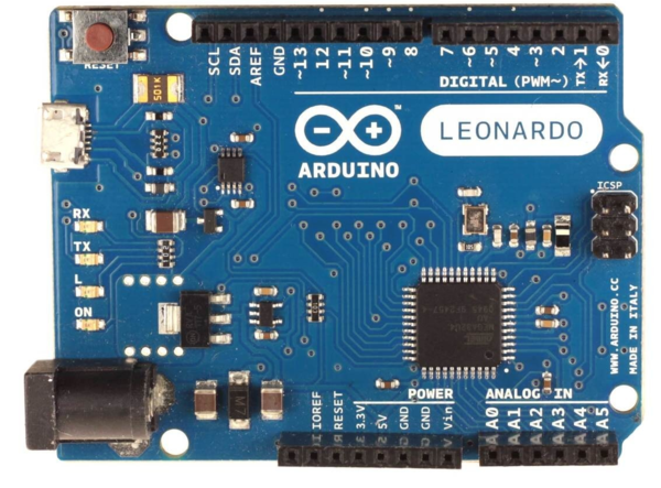
Why the Arduino Leonardo
Initially I MIDI-fied the keyboards with an Arduino Uno, the original board in the Arduino family. However this required an external
MIDI to USB adapter cable costing more than the Arduino and tied up two of the Arduino's digital lines (A0, A1) for TX/RX, although
only TX was used here.
I then discovered the Arduino Leonardo, a variant of the original Arduino Uno that allows the keyboard to appear at the USB port as a
USB device without any programming required, while not impeding the normal operation of the Arduino IDE compile/upload process via the
USB port, something that is not easily achievable with the Arduino Uno. The MIDIUSB library from Gary Grewal (install from the
Arduino IDE Library Manager) takes care of MIDI communication via the USB port. Note that the USB communication protocol is
completely different to traditional serial communication, with all data transfer initiated by the host computer on a polling basis.
This is why is is possible to connect multiple devices in parallel using a simple USB hub, very useful when converting old organs to
Hauptwerk and something one cannot do with serial ports.
Why use multiple Arduino Leonardos
I have described how to use the Arduino in specific cases, where the organ hardware lends itself to interfacing more than one
keyboard to a single Arduino. However when starting from scratch with keyboards and pedalboards that just have electrical contacts
and nothing else, or perhaps already wired up in an 8x8 diode matrix but nothing else, then the lowest cost and most practical
route is to wire up the 8x8 matrix if not already created and then simply connect the sixteen lines directly to the Arduino. If
Arduinos costed $100 or more then it would be cost-effective to use just one and implement external circuitry using 74138s (as with
the Ahlborn example). However Chinese copies of the Arduino cost $10 and it is cheaper and simpler to use one for each keyboard and
pedals (and another for stops and thumb/toe pistons if you have them on the console) than to create an expansion board with 74138s.
Each Arduino can be mounted close to each keyboard and the pedals, avoiding inter-cable capacitive problems if long cable runs
were used.
Simple Scan
The keyboard contacts are wired up as an 8x8 diode matrix and connected directly to an Arduino Leonardo, using pins D8-D11 plus A0-A3
to drive the rows and D0-D7 to sense the key presses. The low cost 1N4148 small-signal diode is well suited and widely used in this
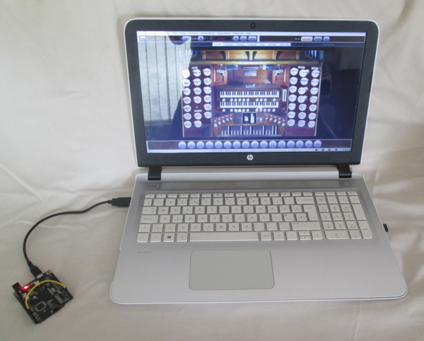
application. The Arduino is powered from the computer so no external power supply is required
(see circuit diagram).
This code example sets up the pins on the Arduino Leonardo as inputs with pull-up resistors or outputs and then loops through the
matrix scan, using a register to save the state of the previous scan and compare it with the current scan so that MIDI signals are
only sent when a key state changes, not when it is held in either state (see code).
As a visual aid to correct operation the on-board LED associated with pin 13 lights when bottom C on the keyboard is pressed. In
addition a short pulse is generated on pin 12 at the start of each loop to synchronise an oscilloscope, both to discover how fast
the keyboard is being scanned and as an aid to troubleshooting.
The same arrangement can be used to scan a 4x8 matrix on a pedalboard. Either modify the code for four rows instead of eight, or
just use the board and code unchanged - it won't find the non-existing rows but will work anyway.
The operation of the Arduino board and scanning code can be checked in isolation, without the need to connect it up to a keyboard.
Just select the board in Hauptwerk Organ Settings >> Keyboards and then use a jumper lead to connect any row to any column and
the appropriate note will sound. Since only one note is being requested at a time it does not matter that no diodes are present.
Debounce Scan
Contact bounce occurs when electrical contacts do not make a clean make or break; this can be due to mechanical bouncing of the sprung
contacts or to corrosion or wear of the contacts. Commonly used electrical contact assemblies used in pipe organs were designed to
switch a high voltage and current into slow-acting solenoids, not microamps at 5 volts into sensitive electronic systems. Modern electronic
organs typically use magnets operating reed relays or hall-effect devices, or conductive buttons and printed circuit board pads as used
in personal computers, none of which suffer from contact bounce or wear, however Hauptwerk is often used to give a new lease of life to
old pipe or electronic organ consoles where the problem has to be addressed.
This is what an oscilloscope trace of bouncing contacts can look like:
Diagrammatically this can be represented by a series of transitions rather than a single clean change.
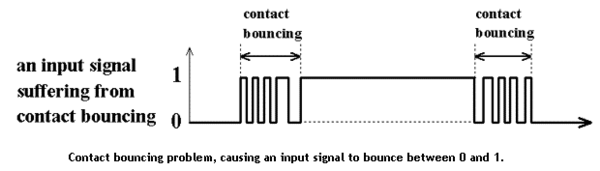
Unless corrected each of these transitions would generate a separate MIDI on or off signal, flooding Hauptwerk with unnecessary commands
and in extreme cases overloading the software, resulting in audio glitches in the generated audio.
A simple solution which works in many cases is to scan the keyboards twice, a millisecond or more apart depending on the maximum length of
bounce, and then comparing the two sets of data for each key. Only when the contacts have settled in their new state will both readings for
each key be the same, and only then is a MIDI command generated. This is not perfect but been found to work well even with badly tarnished
or corroded switch contacts. The separation between scans should be sufficient to correct bouncing but not so long that the overall keyboard
scan rate is reduced to such an extent that a perceptible lag is heard between pressing a key and hearing the resulting sound (latency).
See debounce code.
Note that for each key the time interval between first and second sampling will be the length of time it takes to scan the whole keyboard
once and then come around to scanning it again, plus any additional time coded between scans.
Of course you may not know if you have a contact problem without an oscilloscope, but if you start to hear audio glitches then you
definitely know you have a problem.
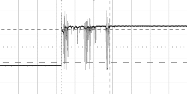
Cable Capacitance and Rise Time
The correct operation of the diode matrix scanning method relies on each row returning high before the following row is brought low,
otherwise unwanted notes will sound. The rows are pulled high through internal resistors (20-50K) on the Atmel microprocessor used on the
Arduino, however
capacitance between the row wires and ground will slow up the voltage rise, to the point that one row is not high before the next is
set low, as this oscilloscope trace shows:
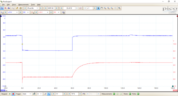
This was demonstrated with an unusually long length of cable by way of experiment, and fixed by adding 1K pull-up resistors:
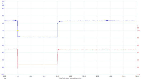
A 100 microsecond delay is programmed immediately after each row has been set to give the row voltages a little more time to
settle down. Each scanning loop takes around 1.6 milliseconds, so the keyboard is scanned over 600 times a second, which is
considerably more than fast enough.
Visual Indication of Activity
Arduino boards have an onboard LED linked to digital I/O pin 13. In organ applications I arrange for the LED to come on when the lowest note on a keyboard or
pedals is played, or the leftmost thumb piston or stop is activated. This provides an immediate visual indication that the keyboard scanning is working correctly.
In addition the TX/RX LEDs flash briefly when any note or accessory is pressed, showing that a MIDI message is being sent or received.
Oscilloscope Sync
Arduino application software runs in a continuous loop, ideally suited to keyboard scanning with very little coding. In organ applications I assign a digital I/O pin
for oscilloscope sync and generate a short pulse at the start of each loop. This is useful for checking the operation of the board, in particular the loop frequency
(how often the keyboard is scanned), which should be at least 100 times a second, and the rise time of the keyboard matrix signals, which can be degraded by capacitance
if the cable from Arduino to keyboard is too long, resulting in spurious notes sounding. See above for an explanation of rise time issues.
USB Connections
When Hauptwerk is running it relies on a permanent connection via USB to the console hardware. It definitely does not like keyboards etc. vanishing and returning,
however briefly. Hence ensure that the USB cables are in good condition, firmly connected to the computer, that the USB sockets in the computer are not damaged or worn,
and that there is no weight on the USB cables at all to cause unwanted contact movement, however minimal.
Issues With Multiple Arduinos in Hauptwerk
Hauptwerk works best when a computer is dedicated to the application and permanently connected to the console. When more than one Arduino is connected then Microsoft
Windows detects them and names them Arduino, Arduino A, Arduino B and so on. If the USB cables are routinely unplugged and later reconnected because the computer is
used elsewhere then Windows has a habit of renaming them, so that for example the Swell keyboard that was previously found on the Arduino A port then turns up on the
Arduino C port. This is particularly likely to happen if the USB cables are connected to the computer USB ports in a different physical order to previously. If this
is likely to be a problem then when setting up Hauptwerk select MIDI IN port: any enabled port in every case. However Hauptwerk Autodetect will
select an individual port, and hence Arduino board, by default, so if the Arduino naming gets swapped around then nothing will work until Hauptwerk is rebooted.
This is not just an Arduino implementation issue, it can happen with commercial organ interface boards too.
Additional USB Issues When Controlling Console From Hauptwerk
When Hauptwerk is just reading MIDI input and more than one Arduino board is used then the above issues need attention but are not critical to the correct functioning
of Hauptwerk. However Hauptwerk can also be used to control console hardware, for example piston and rocker stop illumination or motorised drawstop movement, by
sending MIDI control messages from the computer to the console.
In this case it is essential for Hauptwerk to positively identify an Arduino board with the physical hardware it is interfacing with, and Hauptwerk can hang if not
correctly set up. The reason appears to be (i.e. not documented) that when Hauptwerk sends a MIDI message to something it expects that something to be set up to
receive it and deal with it, and probably return a response of some sort. It is no good Hauptwerk sending a control message scatter gun fashion to all and sundry
and just hoping something grabs it and handles it properly.
While it is possible to identify which of Arduino, Arduino A, Arduino B etc. should be selected in Hauptwerk for a particular MIDI Out function, it falls over
if next time Hauptwerk is fired up the Arduino board naming in Windows has altered as described above. It becomes essential to have some control over board naming.
There is nothing in the Arduino IDE software development environment to achieve this directly. However it can be achieved indirectly. This is a hack to solve this
issue without having to recompile the boot loader (which is what most people say you need to do).
In Windows there is a file called boards.txt in C:/Program Files (x86)/Arduino/hardware/arduino/avr. This contains configuration data on every type of Arduino
board for use in the Arduino IDE. Firstly make a backup in case something goes wrong. Then search for the Leonardo section (leonardo.name=Arduino Leonardo, not
leonardoeth.name=Arduino Leonardo ETH).
To rename the board change:
leonardo.build.usb_product="Arduino Leonardo"
to (for example):
leonardo.build.usb_product="Arduino Leonardo Swell"
Any short ASCII text string will do. You don't have to include the words Arduino or Leonardo.
Then look for the line:
leonardo.pid.0=0x0036
The correct PID (Product ID) for the Leonardo is 0x0036 and this does not need to be changed for the first board. For subsequent boards increment the PID to
0x0037, 0x0038 etc. Now when you launch the Arduino IDE, you should see the new board in the Tools > Boards menu, and when you next upload your sketch (i.e.
program the board) the new name and PID will also be written to the board. Note that if you use a PID that is already used by another device, Windows might
try to install the wrong driver, but in practice PIDs up to 0x0039 have been fine in my projects. Here is a list of Arduino registered PIDs for information.
Note that you are not allowed to change the name and use Arduino LLC's USB VID (Vendor ID). You would have to join the
USB Implementers Forum and
register a Vendor ID yourself.
This hack just assumes you are doing this for your private use and not reselling the Arduino boards. All manufacturers of USB peripherals have to register
both their company (VID) and the PID of each individual product they put on the market with the USB Implementers Forum to ensure each product has a unique
USB signature and that plug and play can download the correct drivers.
Here is an example from my own house organ. I use two Arduino Leonardo boards, one for manuals
and thumb pistons renamed "Arduino Leonardo Manuals", the other for pedals and swell pedal renamed "Arduino Leonardo Pedals". These names then appear
throughout Hauptwerk settings. Note that the Manuals board does most of the work, the Pedals board does very little, but it is convenient to locate
each board near the console components they are interfacing, thus minimising the amount of wiring needed.
TIP: You can verify the renaming of Arduino boards via the Windows Control Panel. Select Devices and search for the boards.
This is where they are on my Windows 11 computer.
Remember: only enable MIDI out in Hauptwerk for Arduino boards that are programmed to accept and process MIDI Out codes (e.g. stop illumination).
Audio Cables
Use good quality shielded audio cables rather than low cost cables which are not fully shielded (where the ground braid does not fully cover the central core).
For example I use
these and
these but not
these.
MIDI Code Debugging
Always have MIDI-OX available. This is an essential tool for tracking down MIDI problems.