Hauptwerk Project 3
Last Updated 3 November 2023
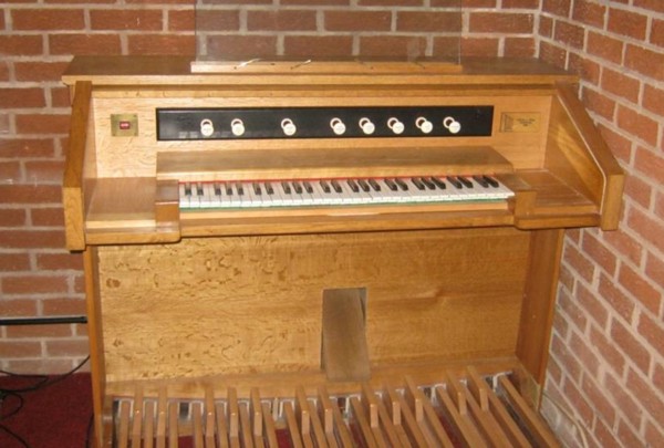
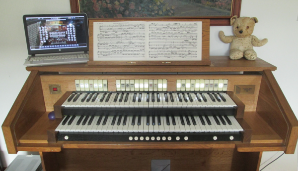
This is a project to repurpose a single manual and pedals pipe organ console to a two manual
Hauptwerk
virtual pipe organ for a local organist to use at home as a practice instrument and for which the St. Anne's Moseley organ that is
included with Hauptwerk would be quite adequate.
The donor console came from a closed church in Bournheath, Worcestershire. This small pipe organ was installed by Tipple in 1998 after
the previous organ was destroyed by fire (NPOR).
Trevor Tipple,
who is now retired, lives in Worcester and devoted his working life to the upkeep and renovation of pipe organs, mainly
in the Worcestershire area, many of them by the long established organ builder
Nicholson
which is based locally in Malvern. In addition he was Organist & Director of Music at St. Martins with St. Peters Church in Worcester
from 1966 to the end of 2018, a remarkable half century of service. He compiled
Organs of the City of
Worcester
in 2005. He was awarded an MBE in 2013 for services to church music in Worcestershire.
New Console Components
The console had presumably been designed for the usual two manuals, and for this application the upper manual had been blanked off. The
initial plan was to fit a second manual, however sourcing a suitable matching 58-note manual proved problematic. At that point a
non-working Eminent electronic organ was advertised locally on eBay and the upper section containing the manuals and electronics was
acquired for parts, along with the swell pedal. The pedalboard only had 27 notes (common with Eminent organs) and was not wanted since
the Tipple console had a 30 note pedalboard already.
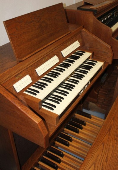
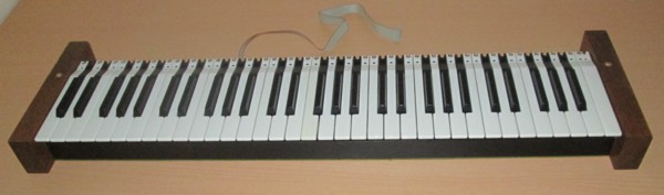
As it transpired the only useful parts were the two manuals, the thumb piston rail, the rocker stops and the the swell pedal, however the
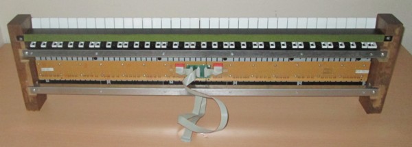
purchase was worth it just for these. The manuals have self-contained contact boards with the commonly used 8x8 diode matrix scanning arrangement
emerging on a 16-way ribbon cable. The electrical contacts use rubber cups with a conducting centre that make contact with exposed pads
on the printed circuit board, a design widely used in modern mass produced electronic keyboards, not to mention the 100 million desktop
and laptop personal computers made each year. These do not suffer from the twin problems of contact bounce and corrosion that afflict older
mechanical switches of all types.
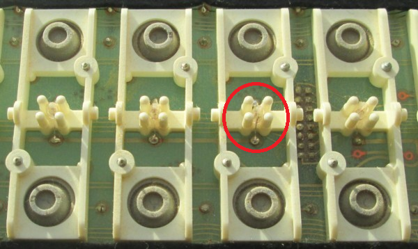
This view of the rocker stops shows the rubber cup with the central conducting pip on the inside, and the black contact areas on the
circuit board that are bridged when the rubber cup is depressed.
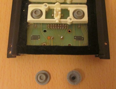
The thumb pistons use the same rubber cup contact method.
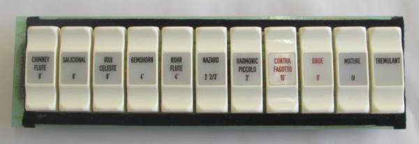
The rocker tab stops are widely used in electronic organs, being much cheaper and easier to interface to electronic circuits than draw stops. They have
separate contacts for ON and OFF and they are illuminated when selected, the minature lamp bulb needing far lower current than the intermittent but much
larger current required for the draw stop solenoid if they are motorised.
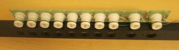
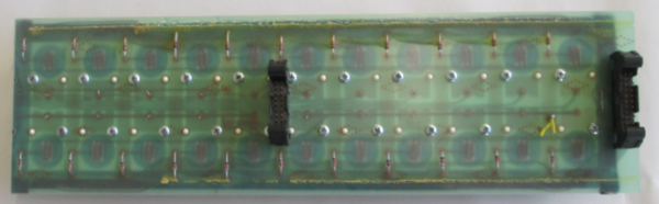
The printed circuit boards are designed for up to 16 stops and can be cut down by the organ builder to suit the console specification. In the Eminent organ
the swell and great each had 11 stops, the pedals 7 stops. The rear shows the matrix diodes and the separate ribbon cable connectors for contacts and
lamps. There was a separate hard wired connection for the lamp supply.
The
latest design of these rocker stop boards
incorporates an on-board microprocessor so that the interface is a simple USB connector,
eliminating untidy ribbon cables, however they cost US$240 each for the full 16 stop board.
The opportunity was taken to replace the minature filament bulbs with 3mm bright white LEDs of the same physical size. The lamps were hard soldered to the
circuit board and it was necessary to unclip the rockers and carefully unsolder each lamp and replace with LEDs without lifting the printed circuit board
track. Replacing a blown bulb on site is evidently a major task whereas the LEDs will last forever and also draw less current. In the interface board the
LED series resistors were chosen for 10mA LED current, compared to 100mA for the filament bulbs. The common LED +5V supply track was linked to an unused
pin on the ribbon cable rather than retaining the separate hard wired cable.
Interfacing to Hauptwerk
Hauptwerk requires MIDI signals from the keyboards, pistons and stops, and also sends out MIDI signals to control console hardware, in this case the
rocker stop illumination. While it is possible to purchase commercially available electronic boards from a number of sources it is far cheaper to use
general purpose hobbyist microcontroller boards like the
Arduino
to achieve the same task, with the added
bonus of complete control of the software functionality.
Each keyboard and the pedal board is wired directly to an individual Arduino Leonardo board, with a further Arduino and custom interface circuits used
for the thumb pistons and rocker stops. The swell pedal is connected to the swell keyboard Arduino board. In theory the entire console could be interfaced
using a single Arduino with extra interface circuitry, however these boards are so cheap that it is simpler to distribute connections and processing
over several boards.
Keyboards
The swell and great keyboards are directly connected to separate Arduino boards, the 8x8 switch matrix requiring 16 of the Arduino's 20 I/O pins. See
circuit diagram. The scanning code for the swell and great keyboards is identical apart from
the assigned MIDI channel. The swell code has an additional section to process the swell pedal. See
swell code and great code.
Swell Pedal
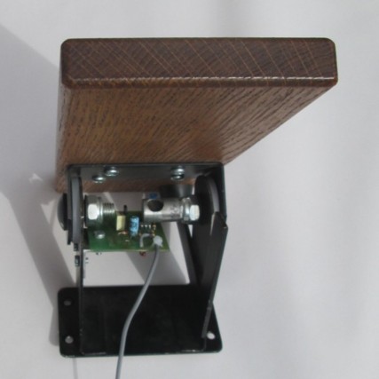
The Eminent swell pedal contains a small magnet which rotates with the movement of the pedal, and the changing magnetic field is detected by
a magnetoresistive sensor and converted into a varying voltage which is connected to one of the analogue inputs of the Arduino board that
also scans the swell manual. See the sensor data sheet and
application note.
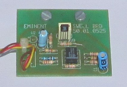
The original circuit was powered from an unknown supply, but the LM7805 5 volt
regulator needs at least 10 volts input. The circuit was modified to
operate off 5 volts for direct connection to an Arduino board which can supply this voltage and also requires analogue inputs to be in the range 0 to
5 volts.
The magnetoresistive sensor device is a Wheatstone bridge whose
output varies by around 25 millivolts in this application as the swell pedal moves from end to end. This is buffered and amplified by the two stage
operational amplifier circuit and outputs a voltage of around 1.15 to 3.65 volts which is connected to one of the Arduino analogue inputs for digital
conversion.
The software code needs to send a single MIDI code when a change in swell pedal position is
detected. However the Arduino analogue to digital converter is a 10 bit device with each level corresponding to less than 50 millivolts, and the
swell pedal circuit was found to output a similar level of electrical noise superimposed on the nominal DC level and this caused the continuous
generation of MIDI signals. This was dealt with by experiment in the software, first by introducing a dead zone or hysterisis in the digital
conversion (which worked), then by averaging 20 readings at a time for digital conversion (also worked), and then for good measure combining
the two approaches. The result is a sequence of around 16 MIDI volume levels (approx #0E - #1E) as the swell pedal traverses its range. The open
wiring was also replaced with a shielded cable.
In Hauptwerk it is easiest to use Auto-detect settings to sense the input (MIDI control changes), channel (01), controller (07 Main volume) and Min/Max
position of the swell pedal.
Rocker Stops and Thumb Pistons
These are controlled with an Arduino board and additional external electronic circuits to sense the switch contacts and drive the stop
illumination. It would be possible to combine the code with the keyboard scannng code on a single Arduino without slowing the overall loop
period so much that latency is audible. However an 8x8 matrix already uses 16 of the 20 digital I/O lines on an Arduino, and in total 10
digital lines are needed to send/receive data and control the shift registers.
Piston and stop scanning is implemented with
CD4014
8-bit CMOS parallel to serial shift registers on one board (see
rocker stop circuit diagram,
thumb piston circuit diagram, and
board construction).
The LEDs are powered by
TPIC6C595
8-bit TTL serial to parallel shift registers on another board (see
rocker stop LED circuit diagram, and
board construction). This is the
code for both. Ultra fast response is not important for stops and pistons and
delay commands are inserted in the code to reduce the scan rate and LED update to around 50 times a second.
Although these boards are hand-built on breadboard it is useful to use printed circuit board design software (in this case the free to use
ExpressPCB Classic) to establish the component layout and track cuts. See
CD4014 board layout and
TPIC6C595 board layout.
The TPIC6C595 was used because it can source or sink up to 100mA, and hence can drive LEDs directly (through current limiting resistors).
A cheaper alternative would be the 74HC595 serial to
parallel shift register. However standard TTL devices can only source or sink a few milliamps, 6mA in this device, and would require
transistor buffering to drive LEDs.
The Ultra bright LEDs used in this application provided good illumination with 10mA current. Note that both the voltage drop across LEDs and
brightness for a given LED current vary significantly between manufacturers, so the series resistor value has to be chosen to suit the LEDs
actually used.
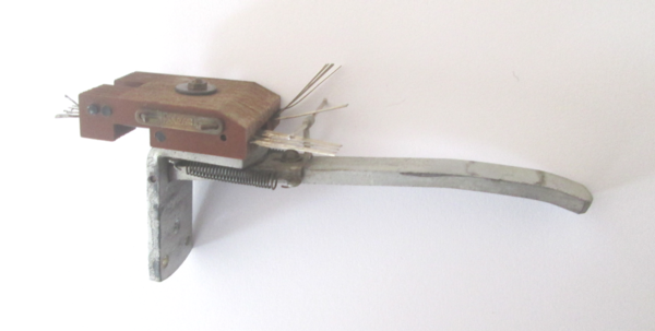
Pedal Board
The Tipple pedal board had been fitted with secondhand pedal jack contacts which were very worn and quite incapable of producing a clean
switching action. The combination of contact bounce and the effect of the T-bar dragging along the individual contact wires resulted in
numerous MIDI messages being generated for each pedal movement, far beyond the ability of software correction techniques. The solution
found was to modify the contacts to make a two-way switch with the pedal jack body becoming the common contact.
Now when a pedal is depressed the very first ON contact is detected by the software which then issues a single MIDI Note On signal to
Hauptwerk. It then does not matter how many subsequent contact bounces occur, nothing further will happen until the pedal is released.
The very first OFF contact issues a single MIDI Note Off signal to Hauptwerk, further contact bounce again being ignored. There are
now 60 contacts instead of the original 30, two per note, and these 60 contacts are arranged in an 8x8 matrix and scanned in the same way
as the keyboards. See switch matrix circuit diagram,
pedal board wiring and
code.
In practice one set of contact wires were bent upwards to form the OFF contact, and the other set bent down a little to form the ON contact.
Since the movement of the T-bar is only 0.2 inches care was needed to get the positioning just right, but once done it seemed to work well.
If contact wires are dislodged accidentally then it is possible for both ON and OFF contacts to be made at the same time, which would result
in a hundred or more MIDI Note On and Note Off messages being generated each second, which would overwhelm Hauptwerk. This condition is
detected in software and MIDI code generation for that note disabled until the contacts are readjusted for normal operation.
The mechanical design of the pedal jack relies on two small coiled springs to return the lever to the OFF position. The spring force of
all eight OFF contact wires combined exceeds that of the lever springs, and this would prevent the jack lever moving to its fully off position.
To deal with this only two of the eight contact wires were actually used (and one would have been fine for this very low current application),
the remaining contact wires being bent out of the way.
Historical note - these pedal jacks have been made by
Kimber-Allen for many years, and are designed to switch large DC currents into
inductive loads in pipe organs with traditional electric action. Hence they have multiple contacts and a sliding action as the T-bar makes contact
to give a self-cleaning action. Modern organ consoles with electronic action generally use non-contact switching (e.g. reed relays or hall effect
switches) combined with up to date digital transmission circuits.
Finally - A Working Console
Here are some notes on setting up Hauptwerk with this console,
including MIDI channel assignment. The existing rocker stop tab labels map closely to St. Anne organ stops in Hauptwerk.
Auto-detect works fine but ensure that the Arduino board used for the stops and pistons has MIDI Out enabled. Do not enable MIDI Out on the pistons and
do not enable MIDI Out on the other Arduino boards.
The Arduino boards must be renamed so that Hauptwerk can correctly identify the one board to send MIDI Out codes to. See
Arduino 101 for detailed technical notes on setting up Hauptwerk to control console components.
In Hauptwerk stop and piston input setup use Stop or Hold-piston: MIDI note-on/off. (Some organs need Momentary Piston:
MIDI note-on to toggle the Sw-Gt, Sw-Ped and Gt-Ped couplers).
The Bass Coupler and Melody Coupler are related. The Bass Coupler adds the selected pedal stops to the lowest note currently being played on the Great.
It's a "cheater's way" of achieving a full organ sound without use of the pedals. The Melody Coupler adds the selected Swell stops to the highest note
being played on the Great, accentuating the melody of the piece being played. This can be a good way to help the congregation hear the melody when they're
singing an unfamiliar hymn, or to help add interest to prelude or postlude music. On the St. Anne organ the Bass Coupler works up to F above middle C on
the Great, while the Melody Coupler works on every note of the Great.
TIP: Do frequent saves (File menu) when going through the Hauptwerk console setup. Hauptwerk can get confused and even hang looking for hardware that
does not exist to process phantom MIDI Out messages.
Afterthoughts
1) The rocker stops must be illuminated when either the stop is operated locally or Hauptwerk decides to turn a stop on or off remotely when it is operated on the
computer screen or a piston, stepper or general cancel is pressed. The way the rocker stop illumination is achieved presents a couple of choices. The purist way is to
arrange for all illumination to be controlled remotely by Hauptwerk, so that for example when a rocker stop tab is selected then Hauptwerk has to recognise that event
and return a MIDI Out signal to the stop to illuminate it. That requires Hauptwerk to be set up absolutely correctly. I chose to operate the LED locally so that the
light will turn on or off under the control of the Arduino software even if Hauptwerk is not running or not configured for MIDI Out messaging. Hauptwerk remote
signalling also works of course. This offers slightly more resiliant operation in practice. In theory there could be contention if local operation and Hauptwerk try to
do opposite things at exactly the same time but this is a remote possibility in practice and not fatal if it does occur.
2) The console is powered entirely from the computer's USB ports. No mains power is required and the original mains switch is not connected to anything (although the
brass plate polished up nicely). The USB standard requires each USB port on a computer to be able to
supply a minimum of 500mA (and most modern computers can supply more). The only real load is the rocker stop LEDs, which have been set to draw 10mA each, so even if
they are all on at once there is plenty of headroom.