Arduino for the Timid
Last Updated 10 June 2024
Arduino boards are very simple to program and use. In fact if you simply want to use the program examples on this web site then you do
not need any software development skills, just follow these instructions step by step to upload software to an Arduino. Note that all
the Hauptwerk examples use the Arduino Leonardo, not the Arduino UNO or any other Arduino variant.
Official Arduino boards come with a plastic mounting tray, while many clones are available, some supplied with a USB cable.
Smaller, non-standard, versions of the Arduino Leonardo are also available. These can be useful where space is limited, although
there is little cost saving over the standard version.
The Arduino Development Environment
Software development and upload is carried out in the Arduino Integrated Development Environment (IDE), which can be downloaded and
installed on your computer. The examples here use a Windows PC but versions for Apple Mac and Linux are also available, and even a
Cloud version. The latest version is 2.x, however the older version 1.x is still available - this is simpler to use and more than
adequate for Hauptwerk related software development and is used here.
Download and install version 1.8.19 from here. Note that both
version 1 and version 2 can co-exist on the same computer.
The first time you launch the IDE you will get an empty project and a default filename based on the date, but you can choose
a more relevant filename before first saving the project. Note that Arduino (curiously) call a software project a "sketch".
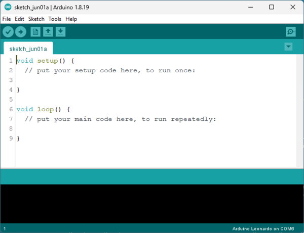
Arduinos are programmed in C (not C++ or C#). The setup section is where you place code that runs
just once when the Arduino is powered up or reset, while the loop section contains the code that will run repeatedly
in a loop thereafter. The black area below is where compile and debug information and error messages are displayed.
Connect an Arduino Leonardo
Connect an Arduino Leonardo to a USB port on your PC. Windows Plug and Play should discover it and assign a COM port to it.
Arduinos of all types are usually supplied pre-programmed with a simple program that continuously blinks the on-board LED,
one second on, one second off. You should see this happening straight away even if the IDE is not running.
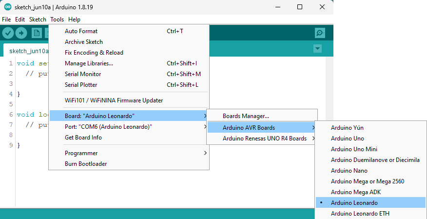
In the Tools menu select Arduino Leonardo from the list of board types.
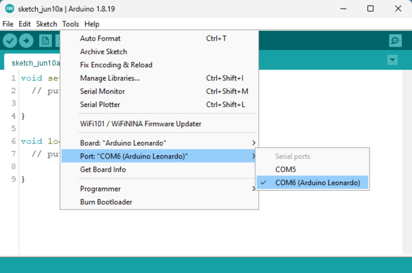
Then from the Tools menu select the COM Port number that your PC has found the Arduino board on. This is from my PC, yours
may look different.
Now you are ready to program your Arduino.
Simple Upload
First follow these simple steps to copy some provided software into the IDE, compile and upload it. You will see how
easy it is to do without knowing how to write software or even having to type lines of code a character at a time.
Click here to see the very simple program that blinks the on-board LED
(opens in a separate window). Delete everything in the IDE code window and cut and paste this code into the window.

Now save the project (File... > Save As...) giving it the name 'Blink'. You will see a file is created called 'Blink.ino'
in a folder called Blink. Keep the file and folder names the same, if you alter one but not the other then the IDE will
complain and create an additional sub-folder.
In the Sketch menu select 'Verify/Compile'. This will first check the C language code for obvious rule and syntax errors
and then if all is well compiles the C code to the native code of the Arduino's microprocessor. The black box will display
a lot of detail, ending with some statictics on the amount of microprocessor memory used.
Errors will be highlighted in red. You can experiment by altering the code until something breaks, for example changing
a single '}' to a double '}}'.
If Verify/Compile went well then in the Sketch menu select 'Upload'. This will verify and compile the C code again and in
addition upload the compiled code to the Arduino. You will see the Transmit and Receive (Tx/Rx) LEDs on the Arduino flash
briefly while the upload is in progress. The black box in the IDE will display even more technical information, including
(confusingly) quite a lot in red which this time does not indicate an error. If the upload fails then check carefully that
you have selected the right Arduino board and port number. In particular the port number might not be obvious, so try each
one found in turn.
The Arduino on-board LED should now be blinking, one second on, one second off. If this was the first time you have
programmed a new Arduino then of course it was already doing this, so nothing obvious has changed. Try altering the
delay interval (in milliseconds, for example change each 1000 to 500 or 250) in the code and repeating the upload to
prove to yourself that the whole verify/compile/upload procedure is working correctly.
That's it! You now know everything you need to be able to program an Arduino board using software that someone has already
written and debugged and then given to you.
Upload a Keyboard Scanning program
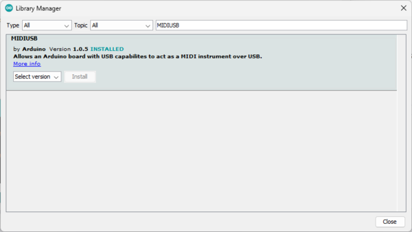
All the software examples on this web site use the MIDIUSB library v.1.0.5 written by Gary Grewal, which is installed from the Arduino IDE Library
Manager. This useful library does all the hard work of assembling MIDI messages and communicating over USB between
Arduino and computer.
The library must first be installed in the Arduino IDE. In the Tools menu select Manage Libraries. Type 'MIDIUSB' in
the search box to locate the correct library. Make sure it is exactly this one, there are several other MIDI over USB
libraries, some with very similar names.
Now you can use the sample code in Arduino 101.
Find the Simple Scan section and click the Code link to display the sample code that will scan an 8x8 keyboard matrix. Cut
and paste this into the Arduino IDE in the same way that you did above with the Blink code. First Verify/Compile the program
to make sure it can find the MIDIUSB library, then upload it to the Arduino.
You have now done everything that I would do if you sent an Arduino board to me to program and I sent it back to you.
The rest is up to you! You will see in the code which Arduino pins are outputs to drive matrix rows and which are inputs to
read matrix columns. In Hauptwerk you will need to select the Arduino board and assign it to a manual in the organ sample
set. Because Arduino boards are low cost it is usually cheaper and more convenient to use one for each organ manual and
pedals rather than trying to scan more than one manual with external circuitry to continuously alternate between manuals.
(In fact I do scan two manuals with one Arduino in Hauptwerk Project 1, but that is because the original console design made it easy to do.)
!!! Remember to program a different MIDI channel number for each Arduino board so that Hauptwerk can identify each keyboard,
pedals, pistons etc. Look for "const byte MidiChannel = n;" in my code where 'n' is the MIDI channel you choose for each board.
If you are familiar with Hauptwerk and all went well with the programming then you can probably go straight ahead and set up
the keyboards etc. However if you are a beginner then you can work through these steps to check an Arduino is working
correctly as a keyboard scanner and then get it going with Hauptwerk.
Link Test
Connect a link between pins A0 and A8 on the Arduino. This corresponds to column 0 and row 0 in the 8x8 scanning matrix, the
lowest note on the keyboard (bottom C).
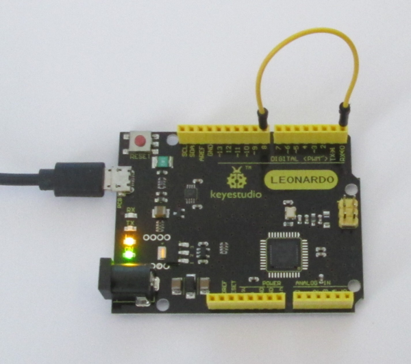
The transmit (TX) on-board LED should flash momentarily when the link is made or broken, indicating that MIDI messages are
being generated and sent over the USB connection to the computer. In addition since this is the lowest note the programmable
on-board LED should light up when the link is made and go out when the link is broken. Linking any other row and column will
flash the transmit LED but not light the programmable on-board LED.
MIDI-OX Test
MIDI-OX is a useful software utility to display MIDI messages. Close
down the Arduino IDE program or Hauptwerk so that nothing else is trying to access the Arduino board.
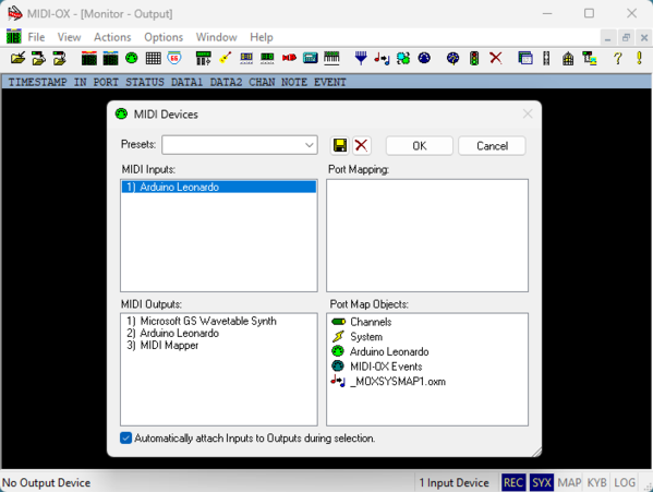
First click MIDI Devices... in the Options menu and select the Arduino board.
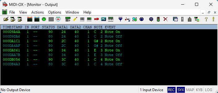
MIDI-OX will now display the MIDI messages produced by the Arduino board, whether by using the simple link wire as above
or playing notes on a keyboard if you have got as far as connecting up the keyboard. In addition to the raw MIDI encoded
data it also usefully shows the actual music note played (C, C#, D etc.).
If nothing is displayed then check that the 'Start or Stop Monitoring MIDI Data' button (traffic light icon) in the toolstrip
has not been clicked.
Hauptwerk Keyboard Setup
If you have got this far then it is safe to assume that the Arduino board has been successfully programmed and is generating
MIDI messages over USB correctly. The following steps are illustrated with Hauptwerk version 4.2 but setting up console
hardware in all later versions is essentially the same.
First ensure that the Arduino IDE or MIDI-OX is not running, then run Hauptwerk, selecting the Free Edition. The exact
sequence of steps encountered depends on how Hauptwerk has previously been used, but the steps shown here assume that this is
the first time Hauptwerk has been used, or has been reset to factory default from the File menu.
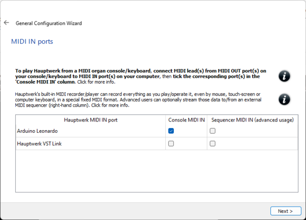
The General Configuration Wizard will run - accept the defaults. The MIDI IN ports screen should have found the Arduino board.
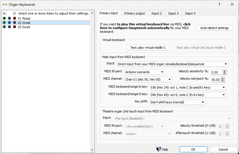
Now load the St. Anne's Moseley organ, accepting the default settings. Right-click the Great (lower) manual and use Auto-Detect
to associate the Arduino board with this manual and define the lowest and highest notes. You can select Keyboards in the Organ
Settings menu to see the settings that Auto-Detect has created (or create the settings yourself manually).